
How to make glowing buttons in VR

When developing experiences for virtual reality (VR), it can sometimes be difficult to guide your player to complete the actions that you want them to do. We aren’t able to simply move the camera to the next point of interest — like you might in a traditional videogame — and UI overlays can often be jarring and break the immersion for the player. While playtesting for one of Magnopus UK’s VR experiences, we found that even prompting the player to press a simple button proved difficult for first-time VR users.
Our initial button implementation used a simple emissive colour property to make it light up, but some of our users were reluctant to press the button. Before resorting to more heavy-handed techniques like UI overlays, we felt that one way to add more agency to the button was to make it feel tactile and more inviting to press — by giving it a rubberised feel and having an LED bulb that would sit beneath the surface — something that would appeal to peoples’ senses.
Buttons can be fun to push in the real-world, but without proper haptic feedback, the best we can do is to overload our visual and auditory senses to compensate and let the player fill in the gaps.
This article takes a look at how we used a simple shader trick to simulate a light that sits beneath the surface of geometry, that is convincingly refracted in stereoscopic 3D.

An example of the interior point light shader at work. Note how the light appears to be sat beneath the surface of the button, and holds up at all angles.
Considerations
As our button was to be used in VR, it was important that the effect rendered stereoscopically. Additionally, the shader needed to be performant and work with UE4’s Forward+ Renderer — which would prevent us from using more physically accurate approaches (such as subsurface scattering), and raised performance concerns about using translucent materials, refraction, and real-time dynamic lights.
However, we were confident that we could approximate these effects entirely in the pixel shader, without the need for any additional graphics buffers, which would allow us to use an opaque blend mode (the cheapest blend mode!).
The following is a tutorial to replicate and implement our solution for rendering this effect in your own projects!
Drawing a 3D sphere in the pixel shader
The first challenge is to render a sphere inside our button, in order to represent the spherical glow from our LED bulb — but before we tackle this, let’s go over how we can draw a circle.
A circle is one of the easiest shapes to draw mathematically, as it can be defined by a single value — its radius. The simplest way to draw a circle in the pixel shader is to test each pixel’s distance from the origin of the circle. If the distance is less than or equal to the radius value, then we should draw the circle for this pixel. If the distance is greater than the radius value, then we should not draw the circle.

Example of drawing a circle in the pixel shader.
Example of drawing a circle in the pixel shader.
To draw a radial gradient instead, we divide the distance by our radius and output the clamped 0–1 values.

Example of drawing a radial gradient in the pixel shader. We apply a one-minus after the saturate so that the output from our circle distance field is more logical (values above 0 = circle, values of 0 = no circle)
A 3D sphere can be described in the same way as a 2D circle — by a radius — and can also be rendered as querying the distance to a point. For rendering a true 3D sphere, we could use a technique called ‘raymarching’, which iteratively tests the distance between the camera and a surface — but this would be overkill for what we need. For our use case, the 2D radial gradient we looked at earlier would suffice if we were to imagine it as a camera-facing sprite — as a sphere would look the same from any vantage point.

Example of using a 2D radial gradient as a camera facing sprite — observe how it appears spherical when in the context of a 3D scene.
Our 2D circle was conceived in UV space, but we want our ‘3D’ circle to appear in ‘world space’ — appearing inside our button’s geometry. To do this, we can draw inspiration from an existing material function in UE4 called ‘SphereGradient-3D’.
This material function computes two key elements:
The first is the distance between the camera and the sphere. This is just the vector length of our camera’s position and the origin of our sphere.
The second is the length of each pixel to the sphere’s centre plane. This is computed by calculating the vector (with its magnitude) from each pixel to the origin of the sphere and finding the dot product of this with the candidate pixel’s direction vector towards the camera.
Once these two elements are calculated, we have enough information in the pixel shader to draw a circle in this view space using the Pythagorean Theorem.
Visualisation of how we use the Pythagorean Theorem to derive the color value for each pixel
We can then scale this by our radius value, to generate the linear radial gradient that appears to exist in 3D coordinate space.

Visualisation of the data used to draw a spherical volume in the pixel shader. Each coloured arrow represents the pixel’s direction vector to the camera. Pictured in the bottom right is the view of the shader from the camera’s vantage point
.By doing all of this work in the pixel shader and only sampling the data we need, we are in effect treating our button geometry as a 2D canvas to draw our shader onto. As a result, we can simulate the effect of something being drawn from within the geometry.
Although you can use the SphereGradient-3D material function straight out of the box to achieve this, you may find it worthwhile building out the logic yourself to get a good understanding of the technique, as this can help inform decisions you make later on in the development of the shader.

The graph for our material function. This is a stripped-back version of Unreal’s SphereGradient-3D material function.
For our button, we pass in the object’s world position as the origin for our sphere, summed with a small vertical offset, as we want our light to appear as though it sits just below the object’s pivot point.

Example of how we compose the location for the button’s sphere gradient — remember, if you want your offsets to be applied relative to the transform of the object, you should use the ‘TransformVector’ node to transform from Local Space to World Space.
Now that we have a spherical gradient, we can start using this data to drive the look of our glowing button!
Styling the glow effect
The falloff for our light source does not look very convincing, so we will want to add some controls for attenuating the falloff. One way to do this is to use a smooth step function, which evaluates a value (such as our normalized, linear falloff) and returns a value from a mathematically described sigmoid function, or ‘S’ curve.

We can then adjust the min/max values of the function to adjust the falloff for our button’s glow. Min/max values that are closer together result in a tighter falloff, whereas values that are further apart result in a softer falloff.

Example of how changing the min / max values of the smoothstep function adjusts the falloff for our sphere gradient
We should also take this opportunity to add some colour to our light. We can make a vector parameter to define our colour, and multiply this with our light falloff. Next, we add a scalar parameter to use as a multiplier for this colour, so that we can overdrive its values so it will be picked up in the bloom pass.

Adjusting the radius, falloff and color values for the sphere gradient really begin to help sell the illusion
Modulating the point light with surface information
We now have what looks to be a light, but it doesn’t currently appear to be sat inside of our button’s geometry. In order to make this effect convincing, we want the light to appear as though it is being refracted and is bouncing about in different directions under the surface.
To do this, we need to query the model’s vertex normal information and use this to offset the origin of our sphere gradient for each pixel. This gives the impression that the light is being refracted, or magnified underneath the surface, and really helps to sell the physicality of the light source and the button.
Example of using the normal information to ‘displace’ the sphere gradient
If you have a normal map for your button, you can also throw this into the shader as additional information to perturb the light. As we are already doing all the work in the pixel shader, this only costs us an additional texture lookup (which you may already be using for the PBR normal output, anyway).

Left: Vertex normal information used to distort the sphere gradient, Right: Vertex and pixel normal information used to distort the sphere gradient
We can also sample an AO map to attenuate the brightness of the button, which helps us to further communicate that this light source is beneath the surface.
And there we have it — finally, a button that looks good enough to touch!

Further use cases
Although this example used a button, this effect scales well to any scenario where you want to simulate the effects of a point light beneath the surface of something — like paper lanterns, or even E.T. ‘s index finger.
You can also use data serialization techniques to encode the locations of your interior point lights into the mesh geometry. This can be extremely useful when you want to draw multiple point lights inside the same geometry, such as a device with multiple back-lit buttons, or maybe a Christmas tree with a string of coloured lights. You could also encode additional data, such as the light radius, falloff, colour, distortion amount, and so on.

Example of how data serialization can be used to draw point lights at multiple points across the mesh. Here, we have serialized the point light positions into the UV coordinates of the buttons in a single mesh draw call. Model from https://sketchfab.com/3d-models/akai-mpk-mini-f7a837c9b469472084940ab3d6609eb2
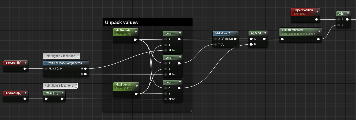
A snippet to demonstrate how we unpack the point light positions before passing it into our material function. This technique is covered in more detail in my How To Populate Real-Time Worlds With Thousands Of Animated Characters post.
Be mindful that although this is a single mesh draw call, the shader is applied to the whole geometry, and as such, we incur the cost for resolving the interior point light for each pixel on the mesh. Therefore, you may wish to consider splitting your geometry into two parts — one that utilizes the shader, and one that doesn’t, depending on whether you are pixel bound or draw call bound.
You could also consider using a thickness map and using this to attenuate the falloff/brightness of your light source to give more accurate results.
In summary, conceptualising your geometry as a canvas for your shader, which you then can additively apply arbitrary data to, can be a really powerful tool and can help you to think outside the box… or in this case — inside the button.
