
Scene-first vs. globe-first: Solving multiplayer world-rendering complexity in 3D environments
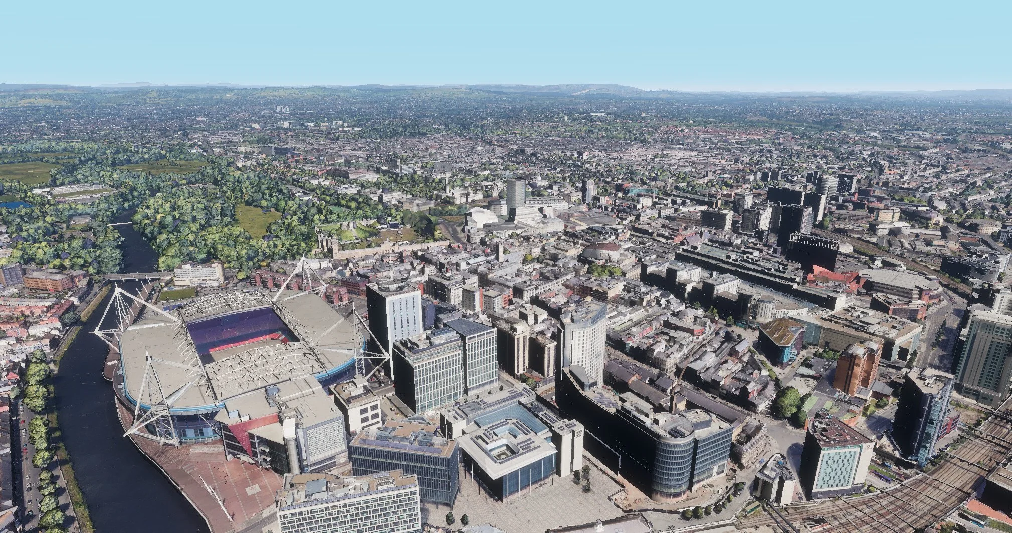
Over the past two years, as our digital twin feature set has evolved, a clear requirement has emerged: users of our spatial intelligence platform OKO need a seamless way to ground their custom assets in real-world environments.
One of the most widely known and accurate representations of the real world is Google Earth, which thankfully also provides an API to access its dataset via 3D Tiles – an open standard defined by Cesium, the platform for 3D geospatial.
What are 3D tiles?
Cesium authored the 3D Tiles specification, which has been adopted by various providers, notably Google and, of course, Cesium Ion.
In simple terms, a 3D tileset is a JSON file structured as a tree of nodes. Each node contains information about a specific region of the world and its geometry. Alongside bounding volumes, coordinates, and detail levels, these nodes can contain either GLTF data, point clouds, or Gaussian splats – the fundamental building blocks used to represent 3D environments.
As an example, an application can traverse the tileset tree by evaluating node bounding volumes and progressively refining into child nodes as the camera approaches an area. This allows highly detailed geometry to be loaded for nearby regions, while larger, lower-detail tiles efficiently represent distant areas
Explored approaches
We identified three approaches to implementing 3D tiles:
Add support for CesiumJS as a rendering engine. OKO was designed from the outset to support multiple rendering engines, including PlayCanvas and BabylonJS. We could add CesiumJS as another option, allowing us to provide our scene data directly to the Cesium rendering context. However, this is a relatively heavy-handed solution for supporting a single feature.
Run CesiumJS “underneath” OKO. The two contexts are then rendered in such a way that they appear as a single scene. However, this approach requires transformations to remain synchronised between the two contexts and introduces a natural separation between them. Bridging this gap would require additional complexity, particularly in scenarios where users wish to modify or replace portions of the world geometry.
Pull the 3D tileset data directly into OKO. In this approach, OKO would parse and render the tileset data within its own rendering context. While this avoids maintaining multiple rendering engines, it adds complexity around tileset parsing, rendering, and the mathematical overhead of ensuring the correct data is where it needs to be.
After a brief investigation, we chose option three: importing and rendering the 3D tileset directly within OKO. This approach allows us to reposition the tiles to fit our scene while minimizing disruption to existing functionality.
The implementation
Typically, a 3D globe application such as CesiumJS or Google Earth renders the globe as the central point of interest, transforming other objects (including the camera) to its surface and orientation. This is effectively a globe-first approach, which makes sense for these applications since the focus is on the globe and other objects are positioned in relation to it.
We took a different approach. To avoid introducing complexity into our multiplayer and cross-platform systems, we kept the coordinates scene-first and instead transformed the globe to sit beneath the scene, placing the globe’s point of interest at Cartesian 0,0,0. This means the space can be rendered in our other deployments, including Unreal and Unity, without any further modification to transformations, keeping the cross-compatibility simple.
The following describes the steps taken to facilitate this.
Loading the correct tiles for the geolocation
Loaders.gl provides the necessary functionality to create a viewport that accurately represents the camera’s position and orientation. We create a MercatorViewport object using the space’s geolocation and the in-space camera’s transform. This allows the library to fetch tiles for the correct location and view frustum, while handling the necessary level-of-detail switches. From there, we hook into tileLoad() and tileUnload() to show or hide the tiles whenever the library signals a change.
Positioning the tiles within a globe
Each 3D tile node contains information such as transforms, model data, and bounding volumes. The GLTF data is parsed into texture, vertex, and index buffers as-is, and positioned within a parent entity using its ECEF (Earth-Centred, Earth-Fixed) coordinates.
Note that no rotation is applied to the individual mesh entities at this stage; their meshes are already authored relative to their position and orientation on the globe. However, within our own data structure, we do store the tile’s bounding volume. Crucially, this includes the rotation required to match the orientation of its mesh – a detail that becomes important later in the process.
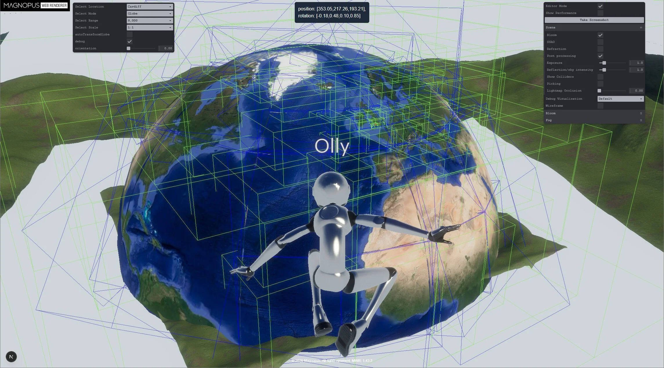
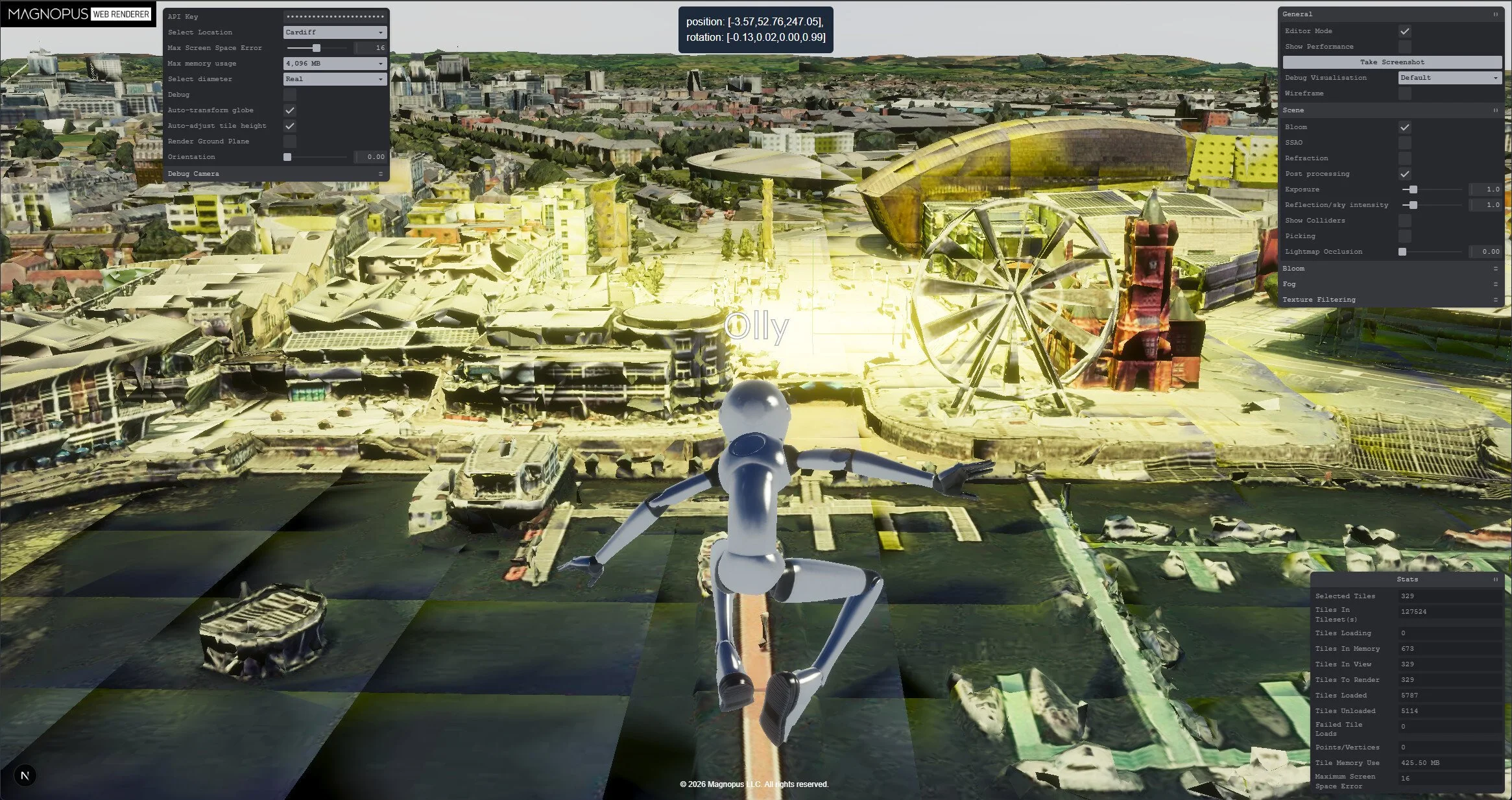
The globe entity, scaled to have a maximum diameter of 300 meters. Meshes are positioned, but not rotated. However, the blue bounding boxes are rotated.
Positioning and orienting the globe
As tiles load in, we identify the one that best represents the space’s geolocation – the “primary tile”. We apply the inverse of its ECEF coordinate to the globe entity, and the inverse of its oriented bounding volume rotation. This rotates the entire globe so that the primary tile sits at the top.
To account for mountains and general elevation offsets, we further adjust the globe’s Y coordinate by the primary tile's bounding volume extent. Note that this can give unexpected results if the tile happens to contain buildings or other real-world geometry. As more detailed tiles become available, we continually reapply this algorithm to keep the primary tile as close to Y=0 as possible.
Separately, we perform a one-time rotation of the globe so that north aligns with -Z in our scene. This ensures that the globe agrees with other mapping systems, such as our 2D satellite map. At this point, despite using separate libraries and data sources, both the satellite map and the globe’s 3D geometry perfectly align.
With just these steps, the scene contains the relevant geometry at a 1:1 scale. The user can walk around the scene (without collision) and add assets using accurate, real-world coordinates.
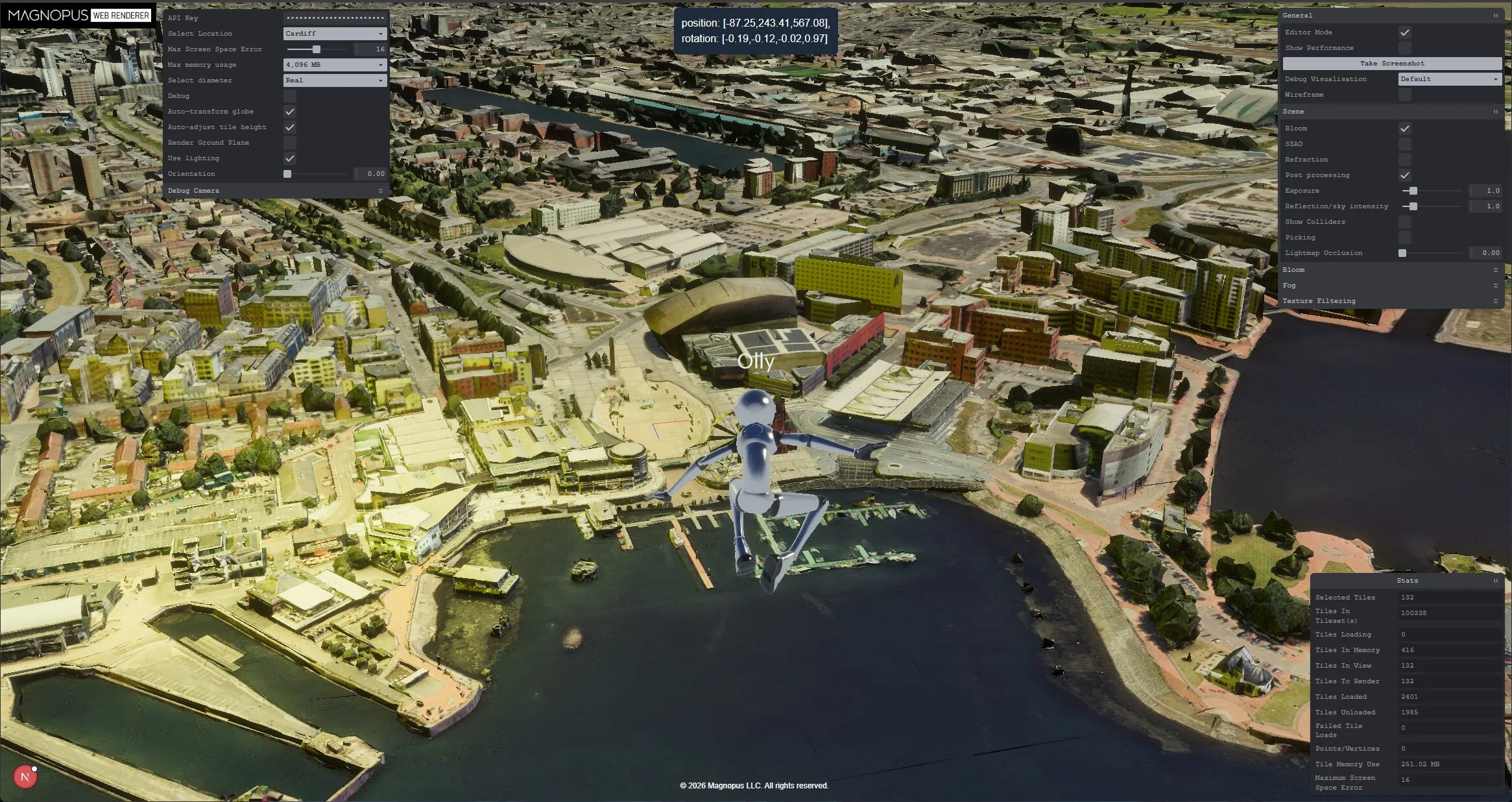
The globe entity, positioned and rotated so the primary tile (the oval-shaped walkway) is Y-up, at 0, 0, 0 in the scene. Note that only the highest level of detail is being rendered here.
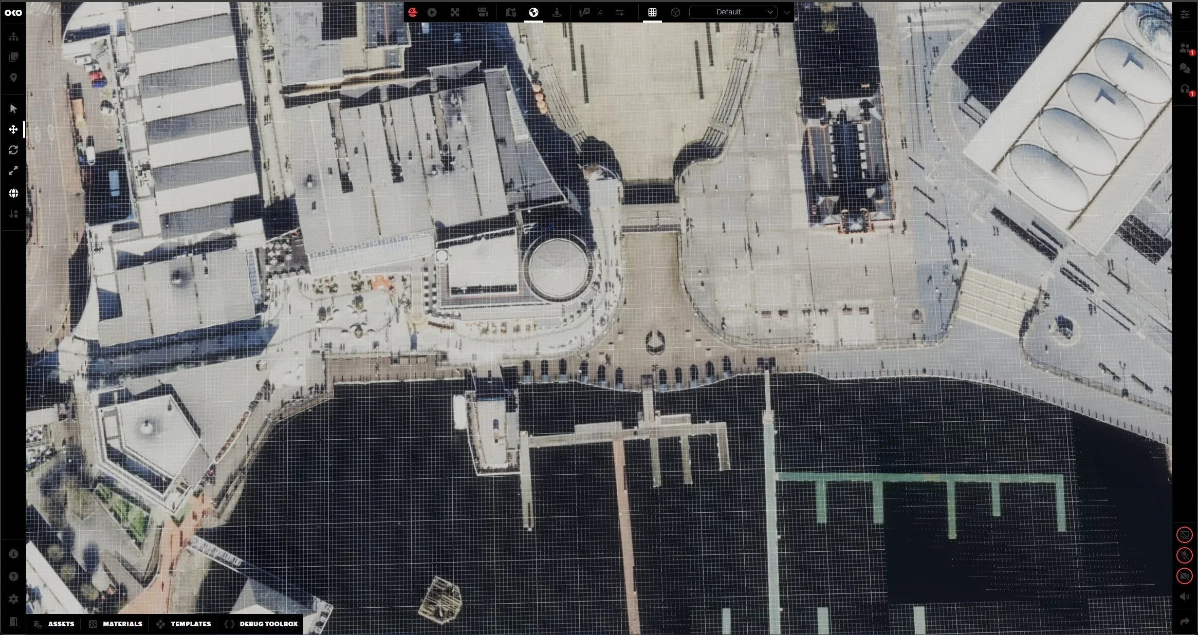
OKO rendering the 2D satellite basemap in a scene. © Mapbox, © OpenStreetMap.
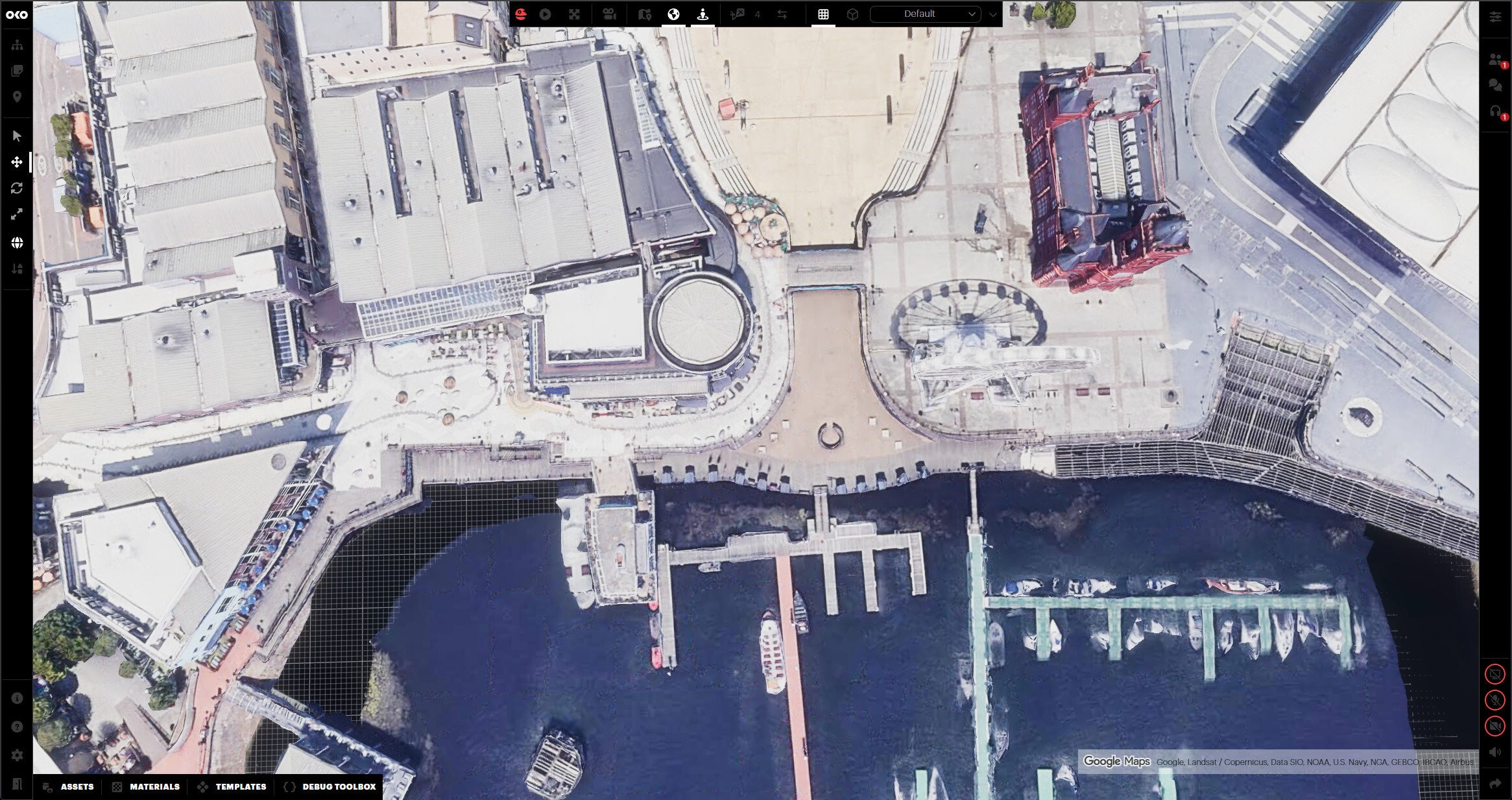
The same scene, with 3D tiles turned on, shows the geometry in the same locations as the 2D satellite map.
Handling lighting
Google’s tileset contains unlit GLTF models without normals. Instead, their textures bake in the real-world lighting captured during photography.
To allow for atmospheric effects like time-of-day, we needed to calculate our own normals, operating under the assumption that we wouldn’t be overriding any existing shadowing.
This was trickier than expected. Standard methods of calculating normals include the tile mesh skirts, which cause visible shading along the tile edges.
To fix this, we use angle-weighted vertex normals to smooth the normals across what can be chaotic meshes, while separately using breadth-first search boundary-edge detection to exclude the mesh skirts from the normals-averaging process.
Using PlayCanvas’ calculateNormals() – tile edges are obvious due to the skirt faces. This is not a bug with their algorithm.
Calculating normals ignoring sideways faces along edges – seams are hidden and buildings unaffected.
Conclusions
As the globe is treated as just another entity within OKO, we can apply all of our existing scripting and workflows to it. This opens up some interesting possibilities:
Transforming to another geolocation: By grabbing the ECEF coordinates of a new geolocation we can interpolate the globe’s rotation and scale. This creates a smooth zoom-out effect before rotating and dropping the user into the new destination.
Adding multiple globe entities: We can technically position two real-world locations side by side. For example, we could place the Eiffel Tower right next to Big Ben, even fetching city blocks and aligning them to create unique mash-ups with minimal code changes.
One important technical consideration is the curvature of the Earth. As a user moves hundreds of kilometers away from the central origin point, the world geometry will naturally begin to tilt beneath the flat ground plane.
While our current projects don’t require users to travel this far, we can manage it by re-applying the globe’s transforms every 100 kilometers based on the user’s position. Since users are already accustomed to level-of-detail shifts as they move, this adjustment to the globe’s underlying transform would be hardly noticeable.
By treating the globe as a dynamic asset within a scene-first architecture, OKO handles massive real-world data without breaking cross-compatibility or multiplayer synchronization. This shift allows users to layer custom interactive elements, multi-user mechanics, and real-world geography within the exact same coordinate system. This solves the traditional complexity of globe-scale rendering by simply turning the world into just another object in the scene.